Voltmat Power
A Power Supply Controller manages how electrical energy reaches a device, circuit, or complete system. It monitors voltage, current, temperature, and operating conditions. Then, it adjusts power delivery when the load changes. This control helps equipment start smoothly, operate efficiently, and avoid unnecessary stress. In a laptop charger, it may regulate charging stages. In an industrial cabinet, it may coordinate several voltage rails and respond to faults within milliseconds.
Small details matter. A controller can sense a sudden current increase before a motor stalls. It can reduce output when heat builds inside a sealed enclosure. Some designs use feedback loops, switching regulators, or microcontrollers for precise control. Engineers often examine datasheets, thermal measurements, oscilloscope traces, and real load behavior before approving a design. Laboratory results are useful, but field conditions can be less predictable. Cable resistance, dust, aging capacitors, and uneven loads may change performance.
A reliable Power Supply Controller should support stable output, protection features, and clear diagnostic feedback. It may include overvoltage, overcurrent, short-circuit, and thermal protection. However, no controller is perfect. Poor layout, incorrect component selection, or weak cooling can still create failures. That is why practical testing remains essential. Understanding these devices requires more than memorizing specifications. It involves connecting electrical theory with real operating evidence, maintenance experience, and honest review of design limitations.
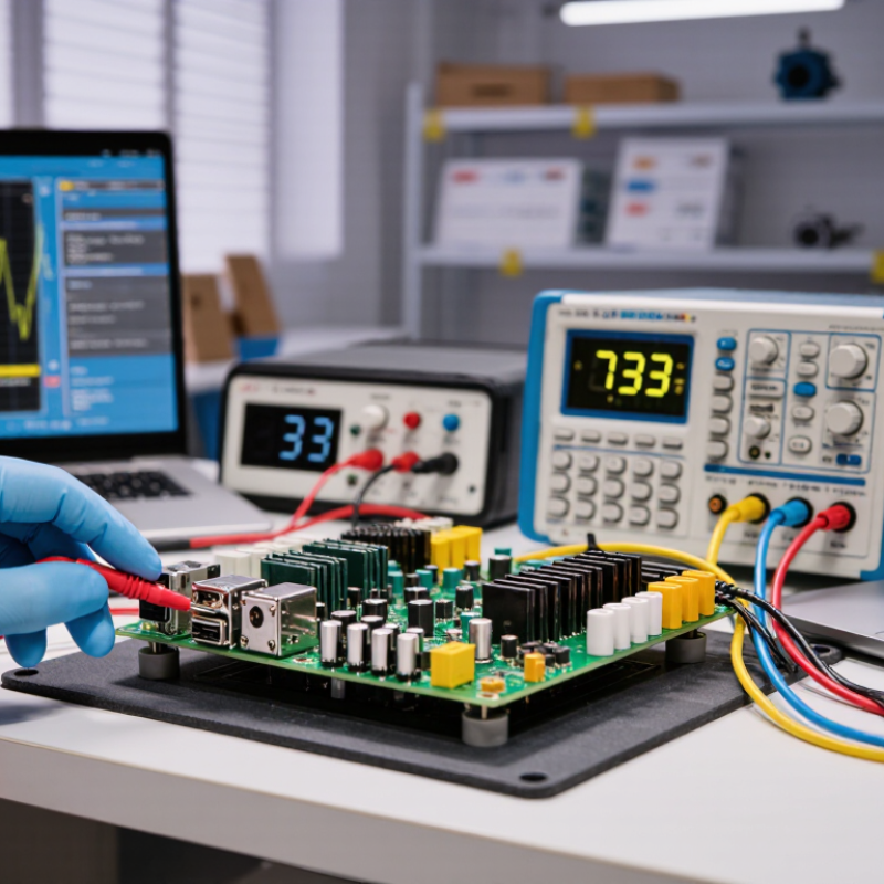
A power supply controller is the decision-making circuit within a power conversion system. It regulates voltage, current, timing, and protective responses. Unlike a passive component, it actively adjusts switching behavior through feedback. This keeps an output rail stable when the input or load changes. It may also control external switching devices, rather than delivering power alone.
It watches constantly. Voltage sensing compares the output with a reference value. The controller then changes pulse width, switching frequency, or conduction time. For example, a 12-volt input may need a carefully controlled 5-volt output. During startup, soft-start timing limits sudden current demand. If excessive current, heat, or voltage appears, protection circuits can reduce output or stop operation.
Engineers typically verify these functions with an oscilloscope, electronic load, and thermal measurements. A stable reading on a multimeter is not enough. Brief overshoot can still damage sensitive circuits. Layout also matters, especially around feedback traces and high-current switching paths. A controller may be technically correct yet perform poorly because of noise or unsuitable timing components. That is where practical testing becomes important. Some designs meet their target on paper but reveal unstable waveforms during load changes. Careful adjustment is often necessary. There is no universal setting.
What Is a Power Supply Controller?
A power supply controller manages energy conversion between an input source and a load. Its main components work together as a closed-loop system. A sensing network measures output voltage and current. A reference circuit provides a stable target value. The error amplifier compares both signals and detects unwanted changes. Its correction signal reaches a PWM controller, which adjusts switching timing. Shorter pulses usually reduce delivered energy. Longer pulses increase it.
The power switch then connects and disconnects the input at high speed. An inductor stores energy during each switching cycle. A diode or synchronous switch directs that energy toward the output. Capacitors smooth the resulting waveform and reduce voltage ripple. Many designs also include a gate driver, current-sense resistor, soft-start circuit, and thermal protection. These parts protect the supply during startup, overload, short circuits, and excessive heat.
Isolation may require an optocoupler or a small signal transformer. This separates hazardous input voltage from the controlled output. In a practical test, an oscilloscope can reveal switching spikes that a multimeter misses. Probe placement matters. A long ground lead may create false ringing. Designers should also check loop stability, because fast feedback can cause oscillation. A supply can meet its voltage target and still behave poorly under sudden load changes. That detail is easy to overlook. No controller design is perfect; component tolerance, temperature, and aging can slowly shift its response.
Common nominal DC voltage setpoints regulated by power supply control systems
A power supply controller uses a reference voltage, feedback circuit, error amplifier, PWM controller, switching transistor, inductor, capacitor, and protection circuits to maintain a stable output. The controller continuously compares the measured output with the target value and adjusts the switching duty cycle. The voltage levels shown are common nominal setpoints used in electronic power systems; actual designs may use different values depending on the load and regulation requirements.
A power supply controller regulates voltage, current, and power delivery inside an electrical system. It monitors changing conditions and adjusts switching devices within milliseconds. This control protects sensitive circuits from overheating, voltage drops, and unstable loads. In practical testing, correct feedback placement often matters as much as the controller itself.
Linear controllers provide simple, low-noise regulation for sensors, audio circuits, and measurement equipment. They waste more energy as heat, especially when input voltage is much higher. Switching controllers offer better efficiency through rapid transistor operation. Buck controllers reduce voltage for processors and embedded systems. Boost controllers increase voltage for displays, lighting, and portable equipment. Buck-boost designs handle input voltages above or below the required output. Battery charging controllers manage charging stages and help prevent excessive current. Motor systems may use controllers that respond to sudden load changes and electrical noise.
Tips: Match the controller with voltage range, output current, efficiency, and thermal limits. Check the data sheet under real load conditions. A circuit that works on the bench may fail inside a sealed enclosure. Keep feedback traces short and away from switching nodes. Measure ripple with suitable equipment, not only a basic multimeter. No controller is perfect. Cost, size, noise, and efficiency always require compromise. A careful designer records these trade-offs before selecting the final circuit.
A power supply controller manages energy conversion, regulation, protection, and startup behavior. Its performance affects voltage stability, heat, efficiency, and system reliability. In practical designs, engineers examine input range, output current, switching frequency, and control method. These values must match the actual load, not only its nominal rating. A circuit drawing 2 A during startup may need far more headroom.
Look closely at transient response and regulation accuracy. A fast response helps prevent voltage dips when motors, processors, or communication modules change load suddenly. Efficiency matters too, especially inside a sealed enclosure. Even a small loss can create noticeable heat over long operating periods. Thermal shutdown, current limiting, undervoltage lockout, and short-circuit protection add useful safety margins. They do not replace proper circuit design.
Selection also depends on layout, component availability, noise limits, and testing access. A controller with excellent specifications may perform poorly beside sensitive signal paths. Check the datasheet’s test conditions carefully. They may not match your board, airflow, or load profile. Bench testing with an electronic load can reveal overshoot, audible noise, and thermal problems early. No controller is perfect. Sometimes, choosing a simpler device improves reliability because fewer settings can be misadjusted. Engineers should document assumptions, test abnormal conditions, and question attractive efficiency figures before approving the design.
A power supply controller regulates how electrical energy reaches connected equipment. It may control voltage, current, timing, or shutdown functions. During installation, technicians should confirm the controller’s rated input and output values. A mismatch can cause overheating, unstable operation, or permanent damage.
Mount the unit on a firm, dry surface with enough space for airflow. Keep wiring short, clearly labeled, and protected from sharp metal edges. Loose terminals are a small detail, but they often create serious faults.
Safety depends on controlled testing. Disconnect all power sources before opening the enclosure, including backup batteries. Use insulated tools and verify the circuit is de-energized with a suitable meter.
Protective grounding must follow the applicable electrical requirements. After installation, test normal operation, overload response, and emergency shutdown features. Do not rely only on indicator lights. They can fail, and I have seen technicians overlook this weakness.
Tips:
Inspect terminals every few months. Look for discoloration, corrosion, cracked insulation, or unusual heat. Clean dust with a dry, non-static-safe method approved for the equipment. Record voltage readings and service dates. Compare new readings with earlier records. Small changes may reveal a developing problem. Replace damaged cables promptly, even when the controller still works. Maintenance schedules are useful, but site conditions matter more. A dusty room, vibration, or frequent power interruptions may require shorter inspection intervals.ceptic?
It is the decision-making circuit in a power conversion system. It regulates voltage, current, switching time, and protective actions. It adjusts operation through feedback. It does not simply deliver power.
A sensing network measures the output voltage continuously. An error amplifier compares it with a reference value. The controller then changes pulse width, frequency, or conduction time. For example, it may convert 12 volts into a controlled 5-volt output.
Common parts include a reference circuit, error amplifier, PWM section, and power switch. Inductors store energy during switching cycles. Diodes or synchronous switches direct energy toward the load. Capacitors reduce ripple. Gate drivers and current sensors add control and protection.
Soft-start limits sudden current demand during startup. Protection circuits respond to overloads, short circuits, overheating, or excessive voltage. They may reduce output or stop operation. That pause can prevent wider damage.
Use an oscilloscope, electronic load, and temperature measurements. A multimeter may show a steady value while missing brief overshoot. Check waveforms during startup and sudden load changes. Probe placement matters. A long ground lead can create false ringing.
Feedback timing, component tolerance, noise, and layout can affect stability. Fast feedback may cause oscillation. High-current paths can disturb sensitive feedback traces. A design can look correct on paper but fail under changing loads. There is no universal setting.
Confirm the controller’s rated input and output values. Install it on a firm, dry surface with adequate airflow. Keep wires short and protect them from sharp edges. Tighten and label terminals carefully. Small wiring mistakes matter.
Disconnect every power source before opening the enclosure. This includes backup batteries. Use insulated tools and verify that the circuit is de-energized. Inspect terminals for corrosion, discoloration, cracked insulation, and unusual heat. Record readings and service dates. Maintenance plans help, but dusty or vibrating locations need closer attention.
A Power Supply Controller is an electronic device that regulates and manages the delivery of electrical power to a system. Its core role is to maintain stable voltage and current while responding to changes in load, input conditions, or operating requirements. Typical components include control circuits, switching elements, sensing mechanisms, feedback loops, protection features, and communication interfaces. Together, these parts monitor power conditions and adjust output efficiently and reliably.
Different types of Power Supply Controllers are used in areas such as industrial equipment, computers, telecommunications, vehicles, and renewable energy systems. Selection should consider input and output ranges, efficiency, response speed, power capacity, thermal performance, control flexibility, and protection against overload, short circuits, and excessive temperature. Proper installation requires following electrical specifications, ensuring suitable ventilation, using secure connections, and observing safety procedures. Regular inspection, cleaning, and performance testing can help prevent failures and extend service life.